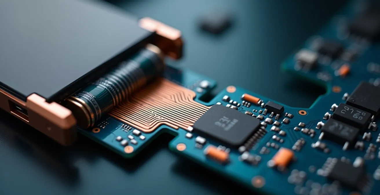
Beyond the glass screens and polished casings of modern electronics lies a hidden revolution—not just in processing power, but in physical form. The drive for smaller, lighter, and more dynamically shaped devices has pushed traditional, rigid circuit boards to their limits. The solution is a technology that bends, folds, and fits into spaces previously thought impossible: the flexible Printed Circuit Board (PCB). This technology is enabled by a co-dependent triad of advanced material science, precision engineering, and an unrelenting demand for three-dimensional design freedom. Working with an experienced flexible PCB manufacturer is crucial to unlocking these advanced capabilities.
This isn’t merely about making circuits bendy; it’s about fundamentally rethinking how electronics are assembled and integrated into our lives. From the smartwatch on your wrist to the complex avionics in an aircraft, flex PCBs are the foundational enablers of next-generation technology, allowing function to dictate form rather than the other way around.
Flex PCB Technology at a Glance
- Flex PCBs enable 3D electronic designs, fitting into compact and unconventional product shapes.
- Polyimide is the key material, providing unmatched thermal and mechanical resilience.
- Manufacturing flex circuits demands specialized engineering to manage challenges like bend radius and signal integrity.
- Future trends focus on sustainable materials and even greater integration with emerging technologies.
The Unseen Revolution: Why Gadgets Demand Flexible Circuits
The global push towards miniaturization is relentless. Consumers expect devices to be more powerful yet smaller and lighter, a challenge that rigid PCBs struggle to meet. This is where flexible interconnect solutions become essential. Emerging trends like the Internet of Things (IoT), advanced wearables, and foldable displays are not just concepts; they are tangible products made possible by circuits that can conform to the human body or fold into a pocket. The flexible electronics market reflects this, with projections showing a CAGR of 10% to $12 billion by 2033.
Flex PCBs facilitate true 3D integration, empowering designers to break free from the flat, two-dimensional constraints of traditional boards. This allows for the creation of innovative product shapes that were once confined to science fiction. This shift in design philosophy is critical for creating devices that are both high-performing and seamlessly integrated into their environment.
The ability to manipulate circuits in three dimensions fundamentally changes the design process. It allows engineers to optimize space, reduce weight, and enhance the durability of connections by eliminating bulky connectors and wires. This capability is not just an incremental improvement but a transformative leap in electronic design.
Flexible PCBs enable truly novel product form factors previously unimagined by allowing circuits to bend, fold, and conform to device shapes.
– IDTechEx Research Report, Flexible & Printed Electronics 2023-2033
The primary forces driving this adoption are clear and compelling. The need for smaller, more functional devices is a constant in the tech industry, and flexible circuits are a direct answer to that demand.
Key Drivers for Flexible Circuit Adoption in Gadgets
- Miniaturization and compact device design requirements.
- Need for high-functionality wearables and IoT devices.
- Demand for lightweight, durable, and conformable electronics.
- Support for foldable displays and 3D integration in electronics.
The Material Science Behind the Bend: Polyimide and Its Crucial Role
The remarkable capabilities of flexible PCBs are not magic; they are rooted in advanced material science. The primary substrate material that makes it all possible is Polyimide (PI). This polymer possesses an exceptional combination of thermal stability, mechanical resilience, and excellent electrical insulation properties, making it the backbone of high-performance flexible circuits. Its ability to withstand high temperatures, including those required for soldering components, sets it apart from less robust alternatives.
What is Polyimide and why is it used in flex PCBs?
Polyimide is a high-performance polymer used as the base material for flex PCBs due to its outstanding heat resistance, mechanical durability for repeated bending, and excellent electrical insulation properties, ensuring reliability in demanding applications.
While other materials like Polyester (PET) exist, they serve more niche, cost-sensitive applications where performance demands are lower. A direct comparison highlights why Polyimide is the industry standard for reliable electronics.
| Feature | Polyimide (PI) Flexible PCB | Polyester (PET) Flexible PCB |
|---|---|---|
| Thermal Resistance | Up to 300°C (reflow capable) | Below 150°C (limited) |
| Mechanical Durability | High, supports repeated bending | Low, prone to breakage if bent repeatedly |
| Transparency | No | Yes |
| Applications | High-performance, high-temp flex and rigid-flex PCBs | Cost-sensitive, low-temp, transparent applications |
Of course, a robust flexible circuit is more than just its substrate. Ancillary materials play a vital role. Adhesives are used to bond the copper layers to the polyimide, coverlays provide insulation and protection for the outer circuits, and stiffeners are selectively added to support components and connector areas, ensuring durability where it’s needed most.
This layered construction, with polyimide at its core, creates a circuit that is both resilient and adaptable. As noted by the technical team at PCBONLINE, Polyimide’s exceptional thermal stability and mechanical resilience make it the backbone of reliable flexible PCBs across demanding industries. This is particularly evident in specialized fields like medicine, where reliability is non-negotiable.
Use of Polyimide in Medical Flexible PCBs
Polyimide-based flexible PCBs are widely used in medical devices due to their biocompatibility, high heat resistance for sterilization processes, and durability during repeated flexing in wearable health monitors.
Engineering for Agility: Navigating Flex PCB Design and Fabrication Complexities
Creating a reliable flexible PCB is a complex engineering feat that extends far beyond simply printing circuits on a bendable material. The design process presents unique challenges that require specialized expertise. Engineers must carefully calculate the minimum bend radius to prevent stress fractures in the copper traces, manage trace impedance for high-speed signals, and strategically place components to withstand dynamic flexing without failure. Properly understanding the underlying hardware components is essential to making these critical design choices.
Overcoming Flex PCB Design Challenges in Consumer Electronics
This study highlights design choices around bend radius, impedance control, and component placement that improved reliability and performance in smartphones using rigid-flex PCBs.
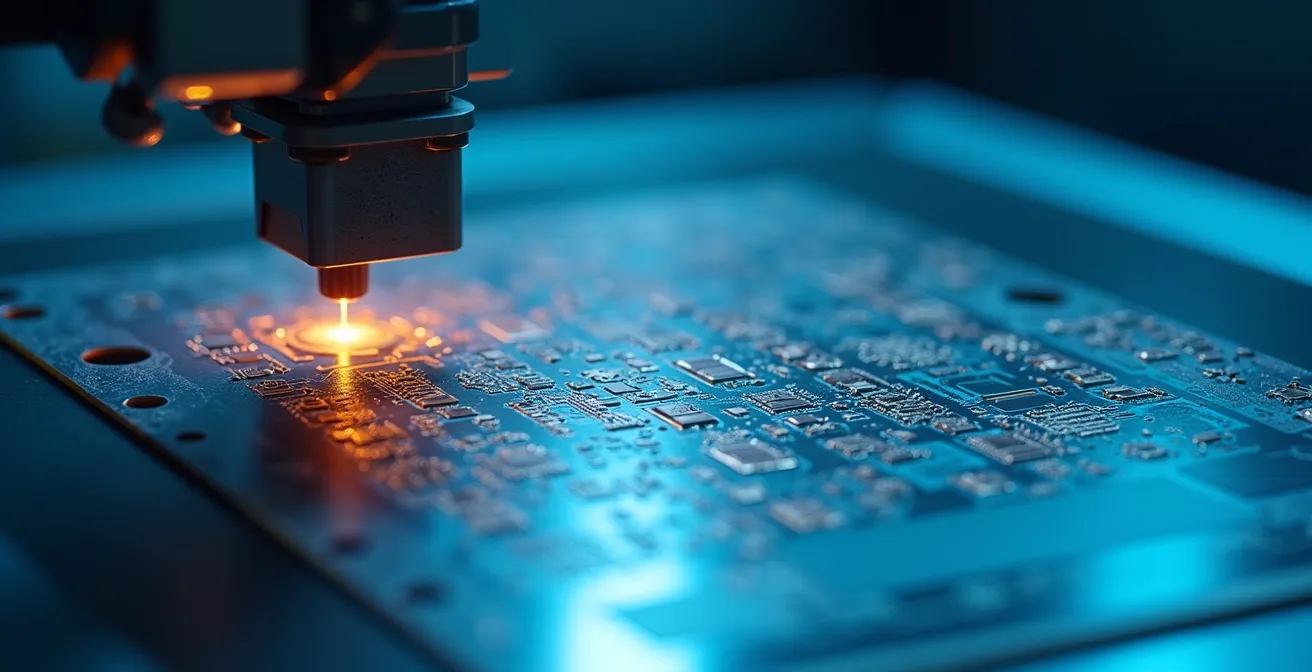
The fabrication process is equally demanding. It involves a sequence of precision steps, from etching incredibly fine copper traces to plating and assembling components onto a non-rigid substrate. The slightest inaccuracy can lead to catastrophic failure, a fact underscored by data showing that more than 90% of defects in flex PCBs originate from manufacturing inaccuracies. This is why selecting a partner with advanced manufacturing capabilities and deep expertise is indispensable for success.
Successfully navigating these complexities requires a holistic approach, from initial design to final assembly. It’s not just about manufacturing a part; it’s about engineering a solution that will perform reliably throughout the product’s lifecycle. To achieve this, it is also important to choose the right computer equipment for design and testing phases.
The manufacturing journey involves several critical stages, each requiring meticulous control to ensure the final product meets stringent quality standards.
Key Steps in Flexible PCB Fabrication Process
- Application of photoresist and photomask alignment for circuit patterning.
- UV exposure and development of the photoresist material.
- Chemical etching of copper to form circuit traces.
- Final cleaning, testing, and surface finishing steps for quality assurance.
Key Takeaways
- Flex PCBs are essential for modern miniaturized and 3D-shaped electronics like wearables and IoT devices.
- Polyimide is the dominant substrate material due to its superior thermal and mechanical properties.
- Designing and fabricating flex PCBs involves unique engineering challenges that require specialized expertise.
- The future of flexible electronics is moving towards more sustainable materials and manufacturing processes.
The Environmental Footprint and Future Trajectory of Flexible Electronics
As with any manufacturing process, the production of flexible electronics has an environmental footprint. However, the industry is actively pursuing innovations to improve sustainability. One of the most promising avenues is the shift from traditional subtractive methods (etching away material) to additive processes like printing. Research from the VTT Technical Research Centre of Finland indicates there can be up to an 86% reduction in environmental impact by switching to additive printing processes.
This shift significantly reduces material waste and energy consumption. Additive methods deposit conductive and insulating materials only where they are needed, creating a more efficient and environmentally friendly workflow compared to the chemical-intensive etching process.
| Factor | Traditional Subtractive | Additive Printing |
|---|---|---|
| Material Waste | High due to etching & cutouts | Minimal, exact deposition only |
| Energy Consumption | Higher due to multiple steps | Lower and streamlined process |
| Use of Critical Materials | Silver-based inks common | Replacing silver with copper/carbon alternatives |
| End-of-Life Management | Less optimized | Design for reuse and recyclability |
Looking ahead, the trajectory of flexible electronics is intertwined with continued material innovation and deeper integration with technologies like flexible displays and sensors. As these components become more advanced, the circuits connecting them must evolve in tandem.
Switching to sustainable production methods and alternative materials is critical for reducing the footprint and supporting circularity in flexible electronics.
– VTT Technical Research Centre of Finland, VTT Study on Sustainable Flexible Electronics
Flex PCBs are poised to continue shaping the evolution of electronics, enabling technologies that are more adaptable, efficient, and seamlessly integrated into the fabric of our world. The focus on sustainability will only accelerate this transition, making flexible electronics not just a powerful technology, but a responsible one.
Innovations in Sustainable Flexible Electronics Manufacturing
Recent advances in roll-to-roll manufacturing and printed electronics drive sustainability improvements by reducing energy use and waste, promoting circular economies in the flexible electronics sector.
Frequently Asked Questions on Flexible Electronics
What is the main difference between a flexible PCB and a rigid PCB?
The primary difference is the base material. Rigid PCBs use stiff substrates like FR-4, making them unbendable. Flexible PCBs use a pliable base, typically polyimide, which allows the circuit to bend, fold, and conform to the shape of a device, saving space and weight.
Why is Polyimide the preferred material for flex PCBs?
Polyimide is preferred for its exceptional thermal stability, allowing it to withstand high soldering temperatures without deforming. It also has excellent mechanical durability for repeated flexing and strong electrical insulation properties, ensuring long-term reliability.
Are flexible PCBs durable?
Yes, when designed correctly, they are extremely durable. Their ability to bend absorbs vibrations and shocks better than rigid boards. Key design factors like specifying a proper bend radius are critical to ensuring their mechanical longevity in dynamic applications.
Can components be mounted on flexible PCBs?
Absolutely. Components can be soldered directly onto flex PCBs. Often, stiffeners made of FR-4 or polyimide are added to specific areas of the flex circuit to provide mechanical support for heavier components and connectors, creating a reliable mounting surface.